

H3C配置
华三交换机命令
基础记了一点常用命令
Vlan 划分与配置
int g1/0/1 #进入接口
int v 10  #进入vlan
v b 10 20 #批量创建vlan
int b 1   #创建聚合口
p link-type t #改变为turk
p t p v 10 #允许不同vlan经过
ip add 10.10.10.10 24 #配置ip地址
双vlan实验
S1
 sysname S1
int b 1
port link-type trunk
port trunk permit vlan all
int r g1/0/9 g1/0/10
port link-aggregation group 1

vlan 10
vlan 20
int g1/0/1
 port link-mode bridge
 port access vlan 10
int g1/0/2
 port link-mode bridge
 port access vlan 20
S2
 sysname S2
int b 1
port link-type trunk
port trunk permit vlan all
int r g1/0/9 g1/0/10
port link-aggregation group 1

vlan 10
vlan 20
int g1/0/3
 port link-mode bridge
 port access vlan 10
int g1/0/4
 port link-mode bridge
 port access vlan 20
Vlan 配置
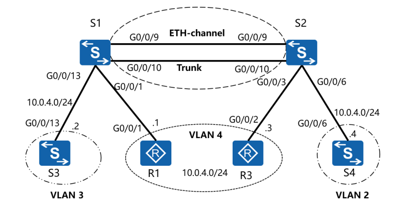
实验拓扑
步骤一
sysname S1
// 创建 Eth-Trunk(Bridge-Aggregation 1)并配置为 LACP 动态模式
interface Bridge-Aggregation 1
 link-aggregation mode dynamic  // 启用 LACP 动态协商
 lacp system-priority 100       // 设置 LACP 系统优先级(全局生效,S1 优先级更低,成为主动端)
quit

// 将物理接口加入 Eth-Trunk 1
interface GigabitEthernet 0/0/9
 port link-aggregation group 1  // 加入聚合组
quit
interface GigabitEthernet 0/0/10
 port link-aggregation group 1
quit
S2
sysname S2
// 创建 Eth-Trunk(Bridge-Aggregation 1)并配置为 LACP 动态模式
interface Bridge-Aggregation 1
 link-aggregation mode dynamic  // 启用 LACP 动态协商
quit

// 将物理接口加入 Eth-Trunk 1
interface GigabitEthernet 0/0/9
 port link-aggregation group 1
quit
interface GigabitEthernet 0/0/10
 port link-aggregation group 1
quit
步骤二
// 进入 Eth-Trunk(Bridge-Aggregation 1)接口视图
interface Bridge-Aggregation 1
 // 配置端口类型为 Trunk
 port link-type trunk
 // 允许所有 VLAN 通过(默认允许所有 VLAN)
 port trunk permit vlan all
quit
三,创建 VLAN,并配置相应的 ACCESS 端口。
S1
int r g1/0/13  g1/0/1
port link-type access
qu
vlan 2
v 3
port g 1/0/13
v 4
port g 1/0/1
S2
vlan batch 2 to 4
int g1/0/3
port link-type access
port access v 4
qu
int g1/0/6
port link-type access
port access v 2
确认S1和S2上已成功创建VLAN,且已将相应端口划分到对应的VLAN中。
display vlan
四,配置IP地址
R1
sysname R1
int g0/1
ip add 10.0.4.1 24
qu
S3
sysname S3
interface Vlan-interface 1  // 华三使用 Vlan-interface 表示 VLAN 接口
 ip address 10.0.4.3 24     // 子网掩码支持位数简写
quit
R2
sysname R3
int g0/2
 ip address 10.0.4.2 24
quit
S4
sysname S4
interface Vlan-interface 1
 ip address 10.0.4.4 24
quit
交换核心堆叠
核心堆叠是一种网络技术,它允许将多台支持堆叠特性的交换机通过专用的堆叠口连接起来,从逻辑上变成一台交换设备,作为一个整体参与数据转发。
SW1配置
irf domain 10	#配置domain域
irf member 1 priority 10	#配置设备权重(大的为主)
int r t1/0/49 to t1/0/50
shutdown		#端口加入之前必须先shutdowm
qu
irf-port 1/1	#irf -port 1/1 注解	前一个1代表交换机的member号,后一个代表irf-port的端口号
port group int t1/0/49
port group int t1/0/50
qu
int r t1/0/49 to t1/0/50
undo shutdown
qu
irf-port-configuration active	#激活配置
save保存
SW2配置
irf domain 10	#配置domain域
irf member 1 remember 2		#重置编号后需要重启设备
qu
reboot
.......
irf member 2 priority 1	#配置设备权重(默认为1,此步可省略)
int r t2/0/49 to t2/0/50
shutdown		#端口加入之前必须先shutdowm
qu
irf-port 2/2
port group int t2/0/49
port group int t2/0/50
qu
int r t2/0/49 to t2/0/50
undo shutdown
qu
irf-port-configuration active	#激活配置
save保存
完成上述配置后,接线,堆叠完成
dis irf		#查看irf配置
dis irf link	#查看irf接口(多用于排错)
IRF 心跳检测(选做)
忘记做了有空记得踢我
静态路由部署与配置
原理:路由器的核心作用是实现网络互连,数据转发,路由器工作时需要建立和更新路由表,因为路由器互联的是不同网段,因此能隔离广播,能快速转发分组数据。
路由表,简单说来就是指挥数据如何发送到目的地的表
实验准备:模拟器 两台路由器,两台PC
拓扑搭建完成后先使用ping测试网络是否连通
当然Ping不通了孩子
这是因为是因为路由无法正常的找到IP地址发送数据包
我们可以先尝试搭建一条静态路由
静态路由
[RAT-1]ip route-static 10.10.20.0 24 10.10.30.2
[RAT-2]ip route-static 10.10.10.0 24 10.10.30.1
成功ping通!
查看一下路由表 可以看到路由已经添加了
dis ip routing-table
除了静态路由的配置方法其实还有一种方法叫做,默认路由
默认路由是一种特殊的静态路由,用于处理所有未知目的地址的流量。它是网络中设备的最后选择
适用于所有未被其他路由明确指定的流量。
默认路由
[RAT-1]ip route-static 0.0.0.0 0 10.10.30.2
[RAT-2]ip route-static 0.0.0.0 0 10.10.30.1
OSPF(Open Shortest Path First)
是一种基于链路状态的内部网关协议(IGP),广泛应用于中大型企业网络中。在华三设备上进行OSPF配置,主要遵循以下步骤和原理:
基本概念
- 链路状态:OSPF通过维护网络的链路状态信息来计算路由,每个路由器都维护着一个链路状态数据库(LSDB),该数据库包含了网络中所有路由器的链路状态信息。
- 区域(Area):为了简化管理和减少路由计算的复杂度,OSPF将网络划分为不同的区域。区域0(骨干区域)是所有其他区域必须连接的区域。
- 路由器ID(Router ID):用于唯一标识网络中的路由器,通常使用一个在自治系统内部唯一的IP地址。
配置步骤
- 启动OSPF进程:在华三设备上,通过进入系统视图并使用
ospf [process-id]命令启动OSPF进程。 - 配置区域:使用
area area-id命令进入OSPF区域视图,指定该区域的ID。 - 宣告网络:在区域视图中,使用
network ip-address wildcard-mask命令将特定的网络加入到OSPF中,以便路由器可以交换路由信息。 - 使能OSPF功能:在接口上使能OSPF功能,确保接口属于某个区域并参与OSPF路由计算。
特点
- 快速收敛:OSPF能够快速检测到网络拓扑的变化,并迅速更新路由表。
- 无环路:由于基于链路状态算法,OSPF保证了路由计算的无环路性。
- 可扩展性:OSPF支持大型网络的扩展,通过区域划分减少路由更新的数量。
通过这些步骤和原理,OSPF能够在华三设备上实现高效的路由学习和转发,确保网络的稳定和可靠运行。
OSPF单域配置
RTA
int g0/0
ip add 10.10.10.2 24
int s1/0
ip add 10.10.20.1 30
int s2/0
ip add 10.10.40.1 30
ospf 10
a 0
net 0.0.0.0 255.255.255.255		#默认路由
RTB
int s1/0
ip add 10.10.20.2 30
int s2/0
ip add 10.10.50.2 30
int g0/0
ip add 10.10.30.2 24
ospf 10
a 0
net	10.10.20.2 0.0.0.3
net	10.10.30.2 0.0.0.255
net	10.10.50.2 0.0.0.3
RTC
int s1/0
ip add 10.10.40.2 30
int s2/0
ip add 10.10.50.1 30
int g0/0
ip add 10.10.60.2 24
ospf 10
a 0
net	0.0.0.0 255.255.255.255
OSPF多域配置
在OSPF中,必须有一个骨干区域(通常为Area 0),所有其他区域必须直接或间接地连接到骨干区域。骨干区域负责在不同区域之间传递路由信息
#ip 地址配置同上
[RTA]
ospf 100
a	0
net 0.0.0.0 255.255.255.255

[RTB]
ospf 100
a	1
net	0.0.0.0 255.255.255.255

[RTC]
ospf 100
a 0
net 10.10.40.0 0.0.0.255
qu
a 1
net 10.10.50.0 0.0.0.255
net 10.10.60.0 0.0.0.255
save
ACL
ACL(Access Control List,访问控制列表)是一系列用于识别报文流的规则的集合。这里的规则是指描述报文匹配条件的判断语句,匹配条件可以是报文的源地址、目的地址、端口号等。设备依据ACL规则识别出特定的报文,并根据预先设定的策略对其进行处理,最常见的应用就是使用ACL进行报文过滤。此外,ACL还可应用于诸如路由、安全、QoS等业务中识别报文,对这些报文的具体处理方式由应用ACL的业务模块来决定
基本ACL根据报文的源IP地址来制订规则,对报文进行匹配
NAPT+telent
拓扑图
内网PC
ip add 10.10.10.10 24
网关	10.10.10.2
内网服务器
int g0/0
ip add 10.10.1.10 24
ip rou 0.0.0.0 0 10.10.10.1.2
#开启tenlent 远程访问服务
telent server enable
line vty 0 4
aouthenticaition-mode scheme
user-role leave-15
qu
local-user xz
passwdorld simple 12345
service-type telent
authorization-attribute user-role leave-15
核心交换
int vlan1
ip add 10.10.10.2 24
int g1/0/2
port link-mode route
ip add 10.10.1.2 24
int g1/0/3
port like-mode route
ip add 10.10.2.1 30
ip rou 0.0.0.0 0 10.10.10.2.2
带宽路由
int g0/0
ip add 10.10.2.2 30
int s1/0
ip add 100.200.1.1 28
ip rou 0.0.0.0 0 100.200.1.2
ip rou 10.10.0.0 16 10.10.2.1
acl nember 2000
rule p s 10.10.0.0 16
nat add group 1
add 100.200.1.3	100.200.14
qu
int s1/0
nat outbound 2000
nat server protocol tcp global 100.200.3[公网] 23 inside 10.10.1.10[内网] 23
公网路由
**int s1/0
ip add 100.200.1.2 28
int g0/0
ip add 20.20.20.2 24**
外网PC
ip add 20.20.20.10 24
网关 	20.20.20.2
此时先在内网测试telnet 服务是否失败**
内网成功访问 telnet
外网PC试一下
大成功!
恭喜你学会了NAT server + telnet!
ppp认证
PAP认证
RTA
int s1/0
linl-protocol ppp
ppp auth-mode pap
qu
local-user xz class network
password simlpe 123456
service-type ppp
RTB
int s1/0
link-protocol ppp
ppp pap local-user xz password simple 123456
MP
RTA配置
int mp 1         #创建MP口
ip add 10.1.1.1 30
qu

int  r s1/0 s2/0
ppp mp m 1
qu

local-user admin class network
passworld simple 123
service-type ppp
qu
int r s1/0 s2/0
ppp auth-mode chap
ppp chap user xz
ppp chap passwd simple 456
qu
RTB配置
int mp 1
ip add 10.1.1.2 30

local-user xz class network
passwdord simple 456
service-type ppp
qu

int r s1/0 s2/0
ppp auth-mode chap
ppp chap user admin
ppp chap password simple 123
验证配置
dis int br
ping 10.1.1.1
期末作业
PC
pc1
ip add 172.10.0.100/24
gateway 172.10.0.254

pc2
ip add 172.20.0.100/24
gateway 172.20.0.254

pc3
ip add 100.0.1.100/24
gateway 100.0.1.254
S2&S3
#S2
v 10
po g1/0/5 to g1/0/8
v 20
po g1/0/9 to g1/0/12
int g 1/0/2
port link-type trunk
port trunk p v all
stp g e
stp m rstp
stp pir 4096

#S3
v 10
po g1/0/5 to g1/0/8
v 20
po g1/0/9 to g1/0/12
int g 1/0/2
port link-type trunk
port trunk p v all
stp g e
stp rstp
S1
v 100
po g1/0/1
v 10
po g1/0/2
v 20
po g1/0/3
int v10
ip add 172.10.0.1 24
int v20
ip add 172.20.0.1
int r g1/0/2 g1/0/3
port link-type trunk
port trunk p v all

int g1/0/1
port link-mode route
ip add 10.0.0.1 30

#stp
stp g e
stp mo rstp
stp pri 0
#ospf
ospf 10
a 0
network 0.0.0.0 255.255.255.255
ip rou 0.0.0.0 0 10.0.0.2
R1
int g0/0
ip add 10.0.0.2 30
int mp 1
ip add 100.0.0.1 30
int r s1/0 s2/0
ppp mp mp1

ip rou 0.0.0.0 0 100.0.0.2
NAT
acl nember 2000
rule p s 172.0.0.0 0.255.255.255
q
nat address group 1
add 202.0.0.1 202.0.0.6
q
int mp 1
nat oubound 2000 address group 1
R2
int mp 1
ip add 100.0.0.2 30
q
int r s1/0 s2/0
ppp mp mp1
ip rou 100.0.0.0 24 10.0.0.6
ip rou 202.0.0.0 24 100.0.0.1
telent
telent server enable
line vty 0 4
aouthenticaition-mode scheme
user-role leave-15

local-user xz
passwdorld simple 123456
service-type telent
authorization-attribute user-role leave-15
S4
v 100
po g1/0/1
v 101
po g1/0/2
int g1/0/1
po link-mode route
ip add 10.0.0.6 30
int g1/0/2
po link-mode route
ip add 100.0.1.254
ip rou 0.0.0.0 0 10.0.0.5
禁止ping
SW1
创建高级ACL
acl ad 3000
rule deny icmp scource 172.10.0.0 0.0.0.255 destination 172.20.0.0 0.0.0.255
rule deny icmp scource 172.10.0.0 0.0.0.255 destination 172.20.0.0 0.0.0.255
int r v10 v20
packet-filter 3000 inbound
禁止telnet
SW1
acl ad 3001
rule deny tcp soure 172.10.0.100 0 destination-port eq telnet
int g1/0/1
packet-filter 3000 outbound
ospf导入默认路由
SW1
ospf 1
default-route-advertise always
qu
undo ip rou 0.0.0.0 0
chap 认证服务
主认证方R2
local-user xz class network
password simple 123
service-type ppp
qu
int r s1/0 s2/0
ppp auth-mode chap#设置认证类型
R1
int r s1/0 s2/0
ppp chap user xz
ppp chatp password simple 123
两个下午做完,ez